Laboratorio de circuitos aritméticos (multiplicador de 4 bit, multiplicador de 2-bit, sumador de 8-bit y un multiplexor de 8 bit)
1. DEFINICION DEL PROBLEMA
Realizar ciertos tipos de circuitos con elementos de almacenamiento y analizar la complejidad del problema, usando la herramienta llamada LOGISIM, que es una herramienta de software libre para diseñar y simular circuitos electrónicos digitales apoyándose en una interfaz gráfica, este software viene con el paquete de licencia publica de GNU, y se puede ejecutar en diferentes plataformas.
En este laboratorio probaremos la funcionalidad de los diseños de los circuitos propuestos en la guía de laboratorio 2, haciendo uso de la herramienta LOGISIM, para realizar los diseños esquemáticos o estructurales de los circuitos y verificar su funcionamiento.
ANTECEDENTES DE INVESTIGACION
Para realizar los circuitos se debe tener previo conocimiento del funcionamiento del software LOGISIM, recordar los principios del uso de este programa que se ha trabajado en la catedra, también se involucra la previa lectura del material de estudio de la clase y la guía del laboratorio, algunas dudad sobre la estructura de los circuitos se resolvieron por medio de búsquedas en internet.
2. PROPOSICION DE HIPOTESIS
Con el programa LOGISIM se realizarán los diseños de los circuitos con elementos de almacenamiento y se probara correctamente el funcionamiento de estos, con ayuda del material de estudio y la guía, se cumplirán los objetivos.
3. DEFINICION DE VARIABLE DEPENDIENTE
En esta práctica usaremos LOGISIM, donde necesitamos la guía de laboratorio, y la colaboración del profesor, definiremos los resultados que deseemos obtener y procedimientos a realizar. El procedimiento del laboratorio será realizado en función de la guía del laboratorio 2.
4. DEFINICION DEL SUJETO EXPERIMENTAL
Dibujando el circuito: Se realizarán los circuitos basados en el diseño y los componentes propuestos en la guía para que el dispositivo funcione correctamente.
Analizando el circuito: Se comprobará el funcionamiento del circuito, proporcionando las tablas de verdad para que las compuertas tengan los números exactos
1. IDENTIFICACION DE VARIABLES INDEPENDIENTES
El desarrollo de:
-Diseño esquemático del ‘Latch D’
-Diseño esquemático del ‘Flip-Flop D’
-Diseño jerárquico de un ‘Flip-Flop T’
-Diseño jerárquico de un registro de corrimiento
2. DEFINICION DEL TRATAMIENTO
2.1 MATERIALES Y SUMINISTROS
LOGISIM
GUÍA DE LABORATORIO 2
MATERIAL DE LA CLASE
2.2 PROCEDIMIENTO
Se procede a realizar los circuitos con medio de almacenamiento según la guía, tomando en cuenta los principios de circuitos con elementos de almacenamiento aprendidos en clase, tomando evidencia de su funcionamiento, y analizando su estructura y resultados para sacar conclusiones en base a la información obtenida en los circuitos realizado.
Diseño esquemático del ‘Latch D’
El Latch D es un circuito biestable asíncrono usado para almacenar información en sistemas digitales, también conocido como latch transparente debido a que el nivel presente en D se almacenará en el latch en el momento en que la entrada Enable sea activada, generalmente mediante un estado alto, es decir 1. Al tener dos entradas para el ingreso de datos se tendrá 4 posibles combinaciones y estas definen el estado de Q como se muestra en la tabla de verdad.
Tabla de verdad Latch D Diseño esquemático del Latch D
Diseño esquemático del ‘Flip-flop D’
El Flip-Flop D es un circuito biestable, resulta útil cuando se necesita almacenar un solo bit de datos,en este circuito Q sigue a D en cada impulso de reloj, para esto el dispositivo tiene dos estados, y la salida es el valor de la entrada D cuando se activa la entrada de sincronismo C y según el modo de activación de esta etrada de sincronismo existen dos tipos, activo en latch(por nivel) y activo de subida o bajada (por flanco), las características de este circuito son aprovechadas para el procesamiento de señales
La tabla de verdad del Flip-Flop D se observa a continuación.
Tabla de verdad Flip-Flop D Diseño esquemático del ‘Flip-flop D’
Diseño jerárquico de un ‘Flip-flop T’
AQUÍ PRRO EDITA DE AQUÍ PARA DELANTE
El multiplicador de 2 bits es el circuito mínimo a realizar para construir una operación aritmética en un simulador o alguna otra herramienta. Como máximo resultado se tendrá «9», y como mínimo resultado se tendrá «0». Las entradas serán A (A1 y A0) y B (B1 y B0). Hay dos maneras de poder realizar esta multiplicación. La primera mediante una tabla de la verdad, las entradas son los dos números a multiplicar y la salida el resultado. La segunda forma es hacer la multiplicación normal y usar semisumadores. En este laboratorio realizaremos el ejercicio mediante la multiplicación.
Tabla de verdad multiplicador de 2 bits Circuito con compuertas lógicas del multiplicador de 2 bits
Multiplicador de 8 bits
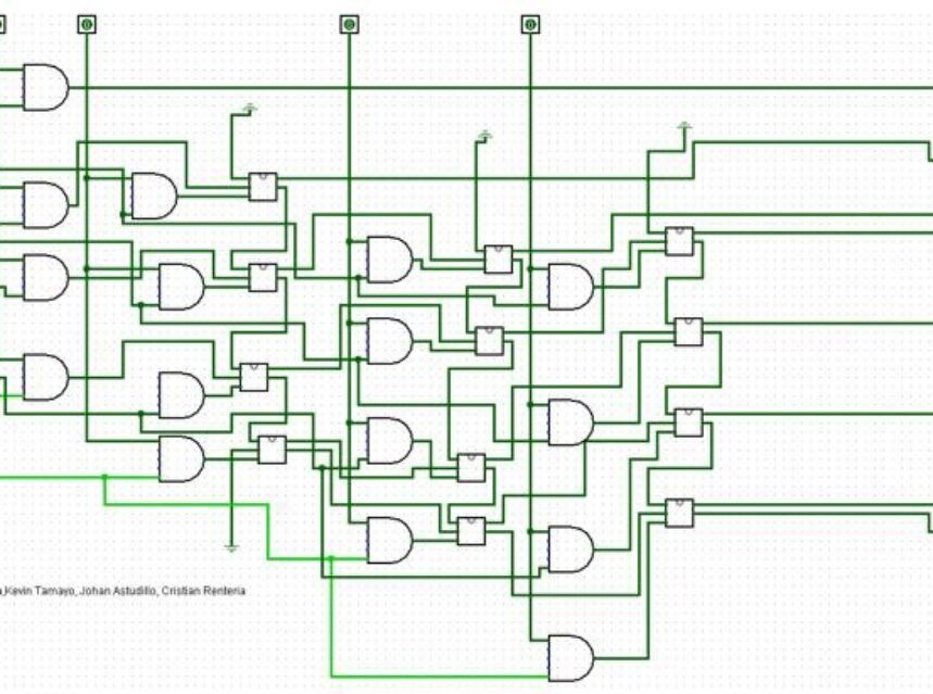
El siguiente circuito es un multiplicador de 2 números de 4 bits. Tiene dos entradas A (A3, A2, A1, A0) y B (B3, B2, B1, B0), que podrán tomar los valores del 0 al 15. Tendrá como mínimo resultado 0 y como máximo 225.
El método usado para el diseño será el de multiplicación directa, es decir primero se realiza todas las multiplicaciones entre bits haciendo uso de las compuertas and, y luego se realizan las sumas haciendo uso de los sumadores. Una multiplicación de 4 bits es como se muestra a continuación.
1. CONCLUSIONES
En este laboratorio se pudo observar el funcionamiento de los circuitos con elementos de almacenamiento y su interacción con los datos satisfactoriamente, mediante el modelado y la simulación en la herramienta LOGISIM, y con esto ver cómo funcionan estos elementos de las unidades de memoria de los computadores comunes


